
PsychoPy is able to communicate with a range of external hardware, like EEG recording devices and eye trackers.
This page provides step-by-step instructions on how to communicate with some of the more commonly used hardware. The page is being updated regularly so if you don’t see your device listed here please do post in the forum as we keep an eye on commonly-faced issues (and solutions!) there.
Before getting started with an EEG study in PsychoPy, we highly recommend reading relevant information on how to measure and understand timing. Although these guides will talk you through how to communicate with EEG hardware, they can really be used to communicate with any device that is connected via the same method:
PsychoPy has a Parallel Port component in Builder view. This can be found in the I/O component drop down. This component supports both traditional parallel ports and USB devices.
If you’d like to use a Parallel Port to record responses (for example from a button box) please read this excellent thread from our Discourse Forum user jtseng.
Add your Parallel Port component to your routine in the same way that you would with any other component:
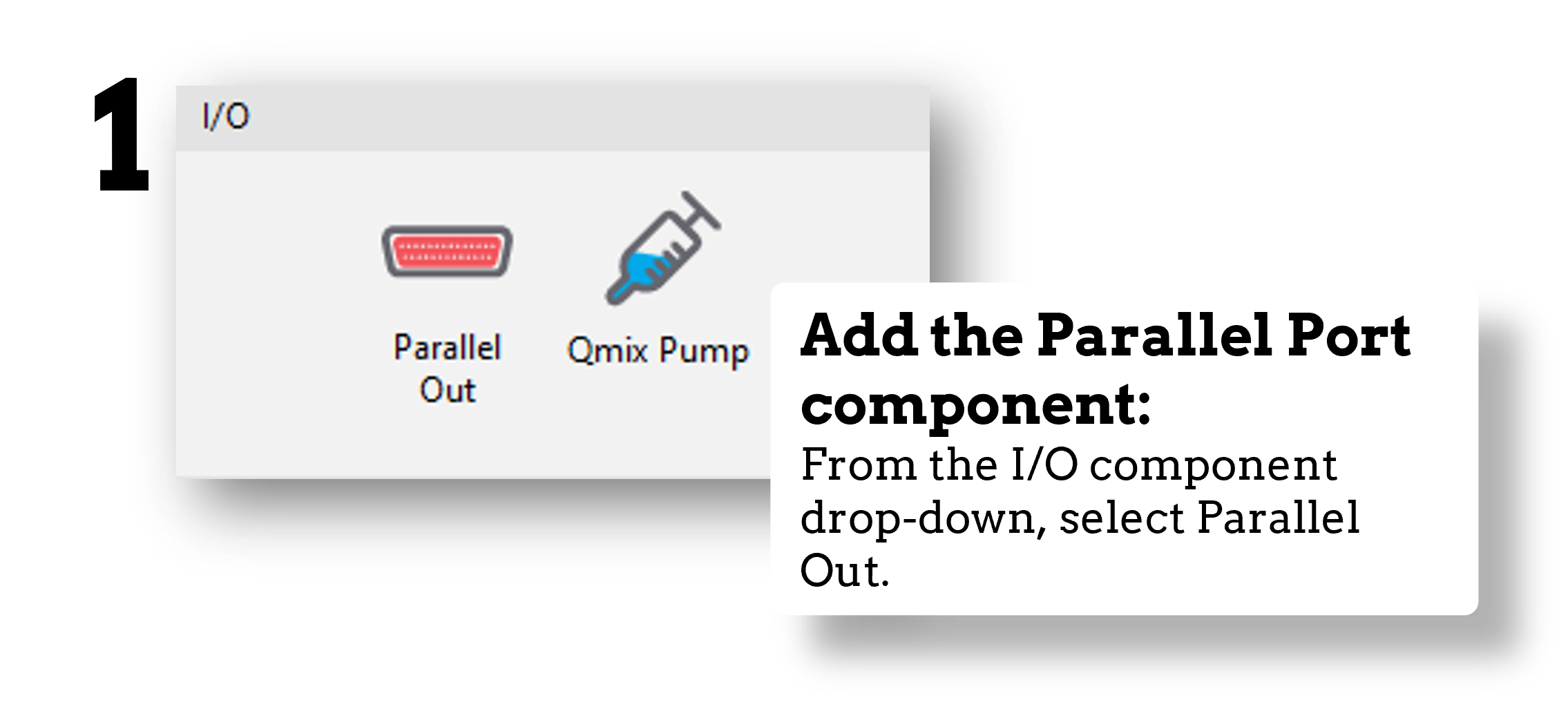
Fig. 5 Select the Parallel Port component from the I/O or EEG component drop-down menus.
Now, imagine we want our trigger sent to indicate stimulus onset. We could do this by simply setting the onset time of the trigger to match that of our stimulus. But this is not the most precise way to do this. Also, this doesn’t help us if we want to send our trigger to indicate something with variable timing, such as when a response is made.
For maximum precision, we’ll set the trigger to be sent when the status of our stimulus is set to started:
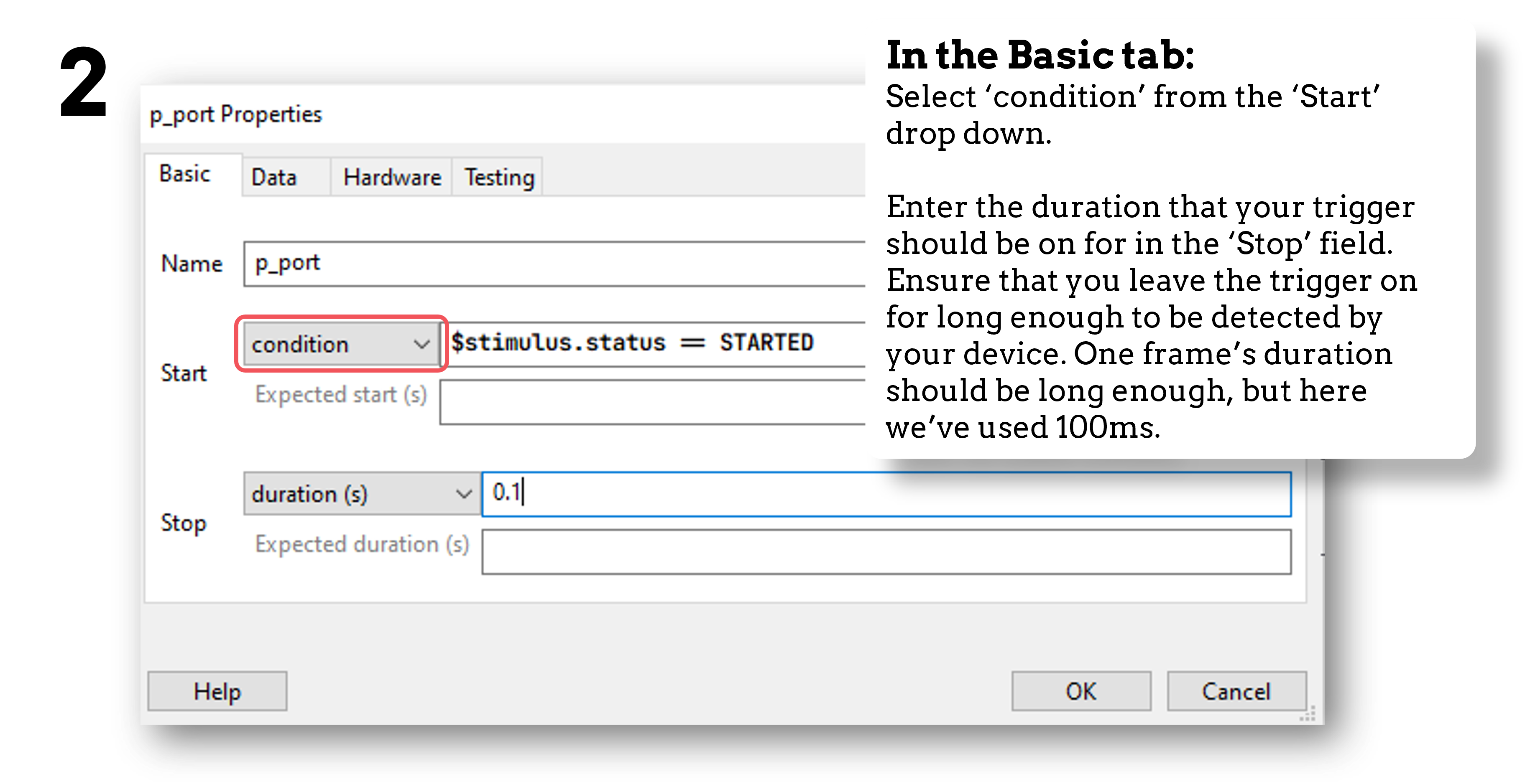
Fig. 6 In the Basic tab, we’ll choose to start our trigger when a condition is met by selecting condition from the Start drop down.
Now we set that condition by inserting the following code:
stimulus.status == STARTED #Change 'stimulus' here to match the name of your own component
Now, in the Data tab, we set the data we want the trigger to actually send:
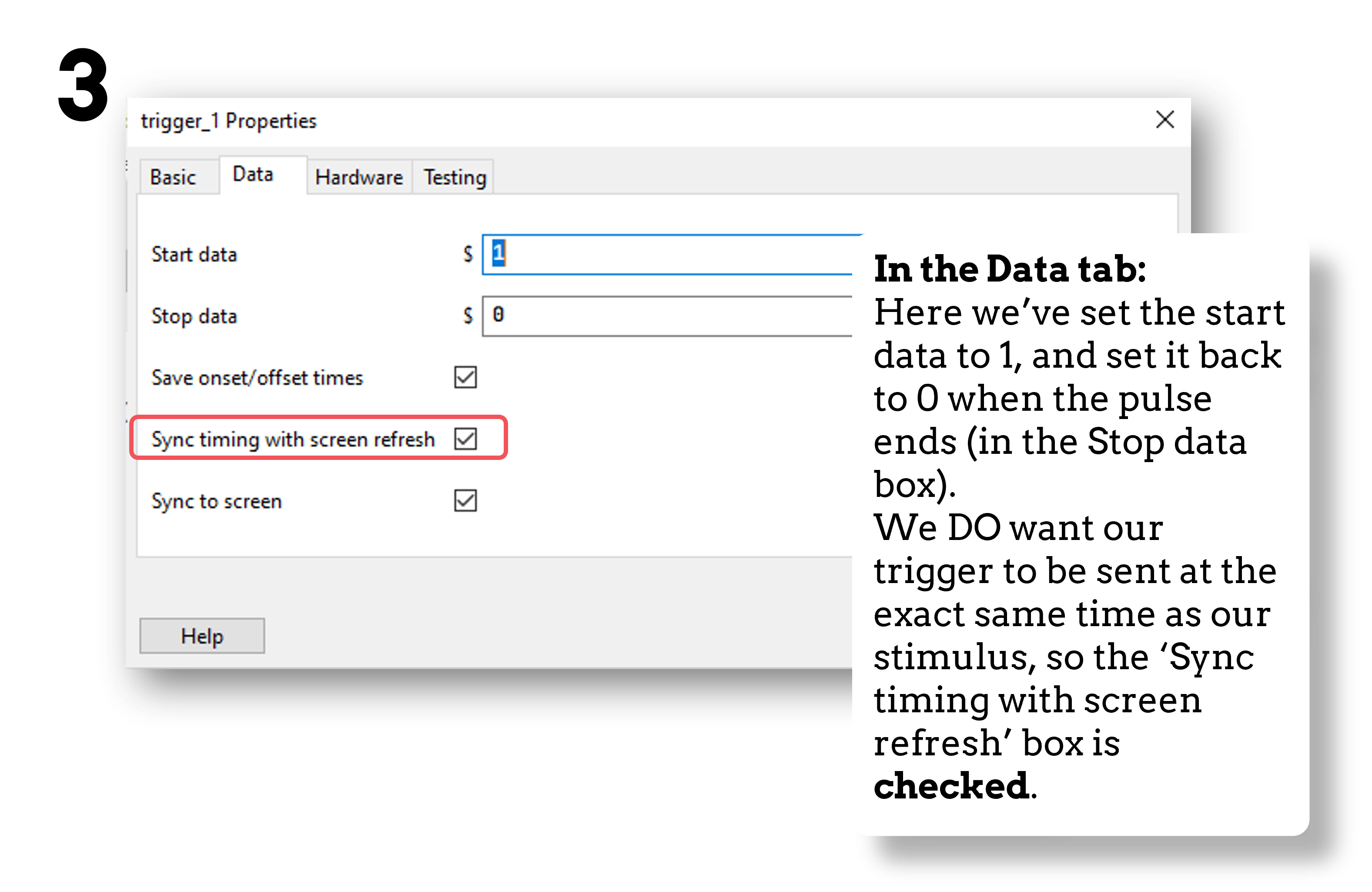
Fig. 7 Set the data to be sent by the trigger
So our component is added and we’ve set it up the way we want. We now need to make sure that the trigger is going to be sent to the right place!
To do this, we’re firstly going to check our port address.
We can check this on our computer (not within PsychoPy itself) by navigating to: Device Manager > Ports > Find the parallel port that you are using from the drop down > Right-click Properties > Resources tab > The port’s address is under the Settings header.
Note
The address of the port is not the same as the name of the port. For instance, the name of the port could be “LPT 1” but the address might be “0378”.
Now, in the Hardware tab of the parallel port component in PsychoPy, select the correct parallel port address:
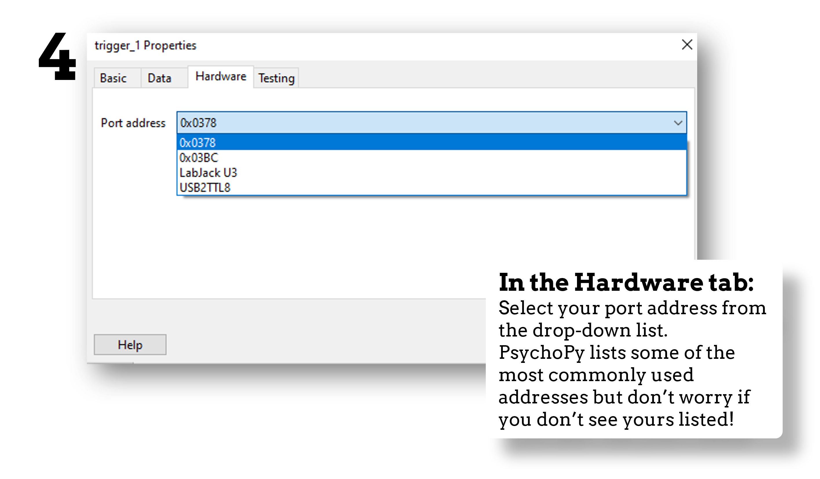
Fig. 8 Select your port from the drop down, if you don’t see it listed just follow the next step.
If you do not see the correct address in the drop down, in PsychoPy navigate to: File > Preferences > Hardware > Parallel Ports > Click the “…” icon > Click the New Item icon > Enter the parallel port address > OK > Apply:
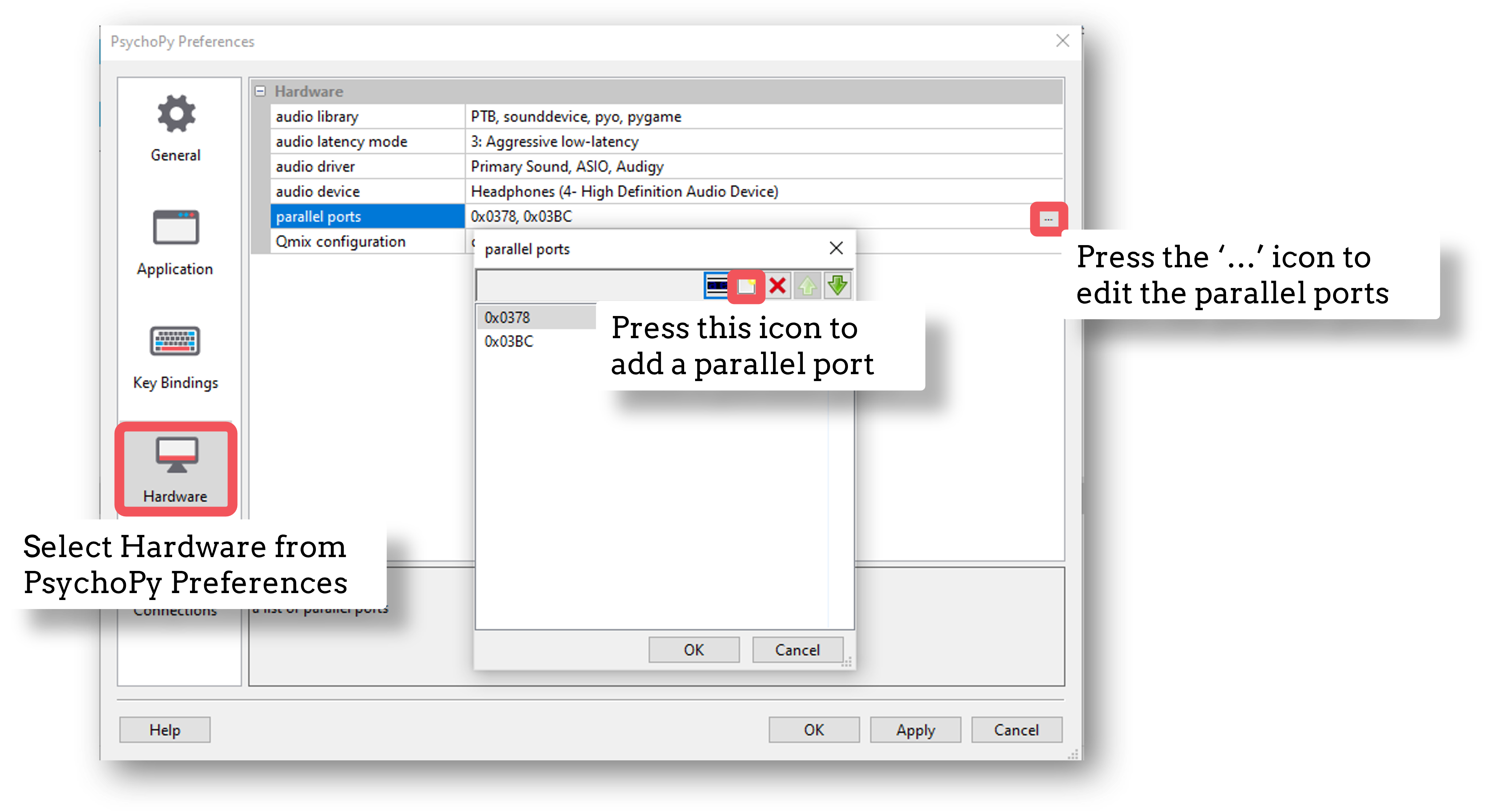
Fig. 9 Follow these steps to add your port address, only if it was not already in the drop-down menu.
Note
The parallel port address is usually a hexadecimal address. We tell PsychoPy to read it as such by prefixing with “0x”. So if your port address appears in Device Manager as “0378-037F” for example, in PsychoPy this would be written as “0x0378”.
The correct port address will now appear in the drop down menu in the Hardware tab of the Parallel Port component.
If you’re using a Mac, it’s recommended that you skip this step. For Windows users, a common error when trying to communicate via a Parallel Port component is that certain drivers are not found. We’re going to pre-empt that error by downloading and installing the correct drivers now.
Download the InpOutx64.dll and InpOutx32.dll files from here. You need to use the “Binaries only - x86 & x64 DLLs and libs” option under the Download Links subheading near the bottom of the page:
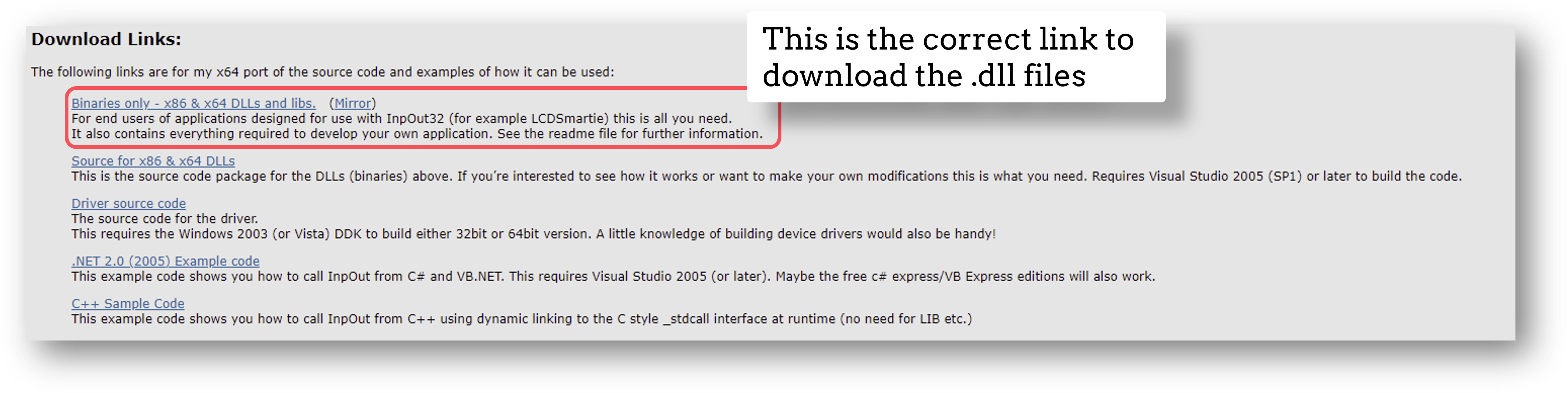
Fig. 10 The correct folder to select is shown here.
When downloaded, find and extract the .zip folder. This will be called something like “InpOutBinaries_1501.zip”.
In the unzipped folder, find and copy the files “inpoutx64.dll” and “inpoutx64.lib” from the x64 folder, and then the file “inpout32.h” from the Win32 folder. Place a copy of all of these in the same folder as your PsychoPy experiment file (the one with the .psyexp filetype).
Restart PsychoPy (save your experiment first!)
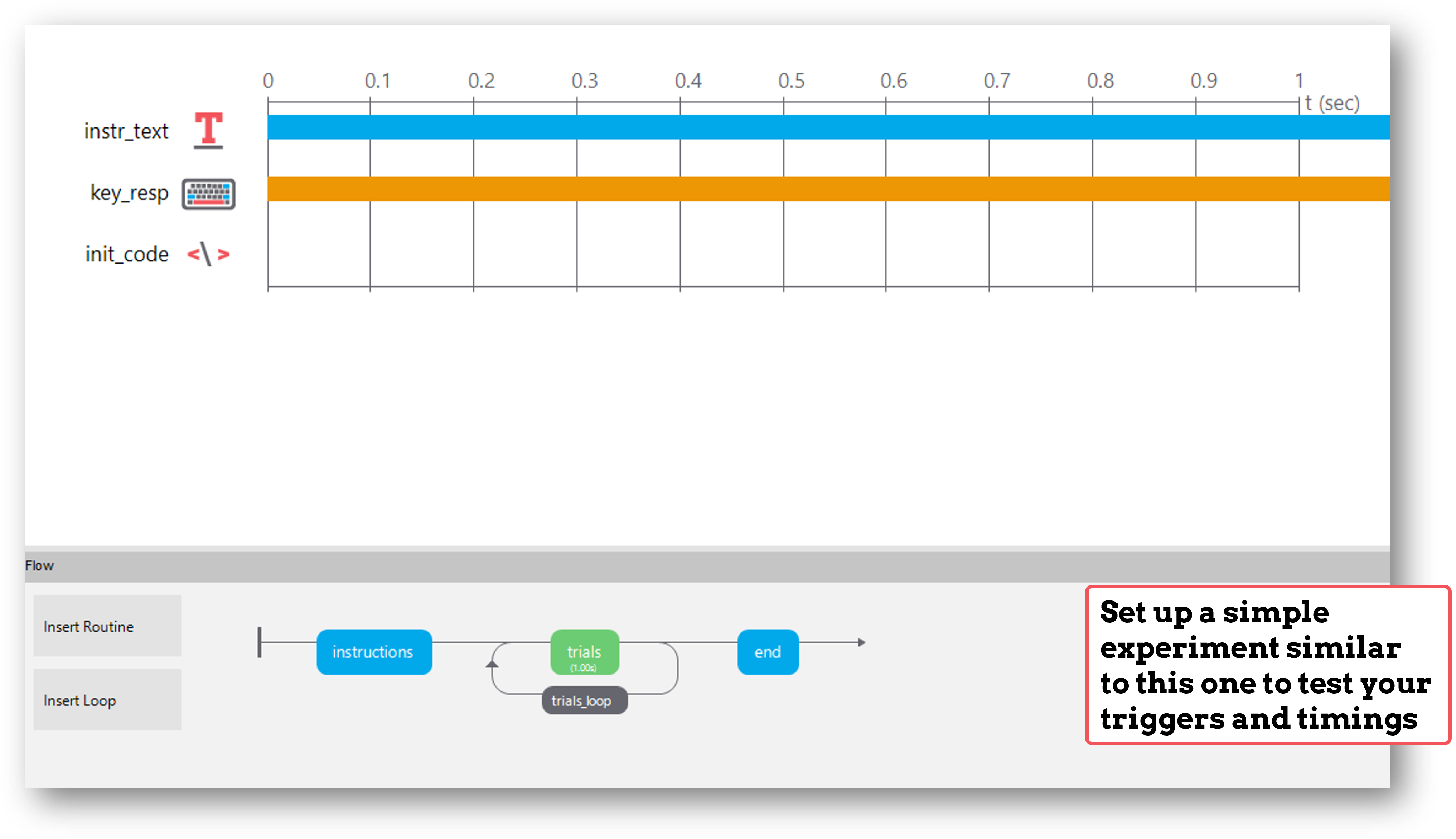
To check that everything works, we recommend that you set up a very basic experiment that looks similar to this:
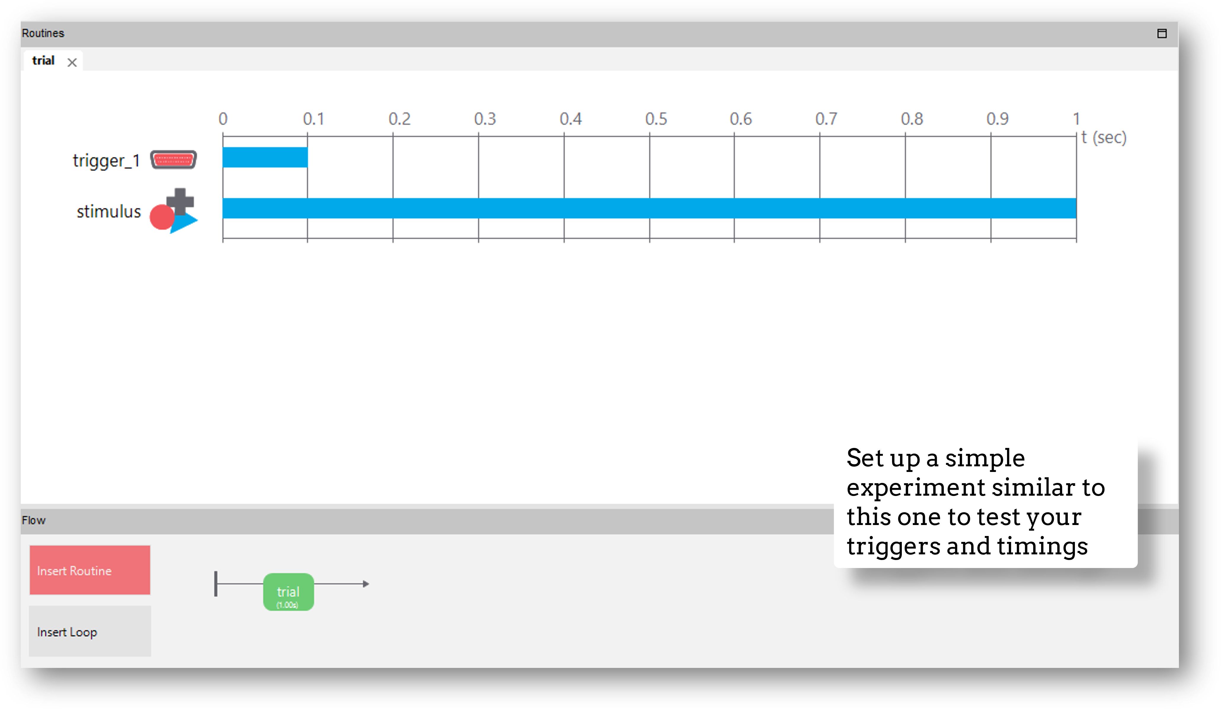
Turn on your EEG recording device and start recording as you would in your actual experiment, and just check that you see triggers coming through.
It’s a good idea at this point to also check the timing of your stimulus presentation and your triggers using, for example, a photodiode for visual stimuli.
Doing these checks with a very basic experiment just means that you don’t accidentally change something on your real experiment file that you don’t want to, and also means you don’t have to disable components or sit through lots of instructions etc!
Note
If you’d like to use a Parallel Port to record responses (for example from a button box) please read this excellent thread from our Discourse Forum user jtseng.
Note that if you are using PsychoPy version 2022.2 onwards, you may use the :ref: serial port component <serial_comp>. If you are using an earlier version you will need to use :ref: code components <serial_code>. For both use cases you will need to know your serial port address.
Serial port addresses are different depending on whether you’re using a Mac or a Windows device:
If you’re using a Mac
Open a Terminal window and type:
ls dev/tty*
In the terminal window, you’ll see a long list of port names like in the screenshot below:
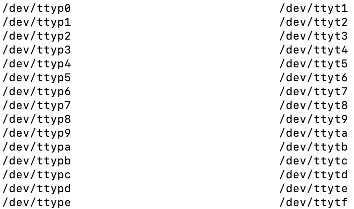
To find out which one your device is connected to, you can remove and replace your device to see which port name is changing.
If you’re using Windows
Open the Device Manager and click on the Ports drop down to show available ports like in the screenshot below:
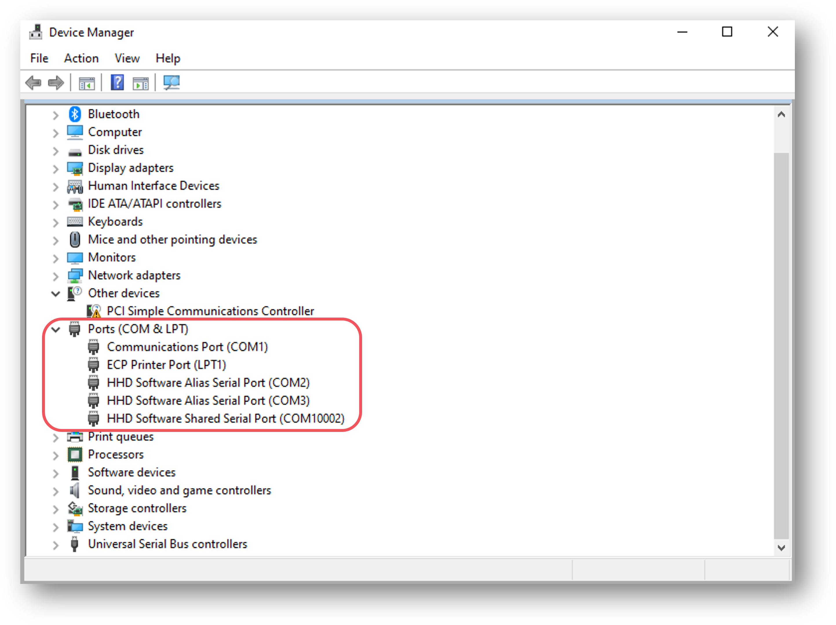
If it’s not obvious which port your device is connected to, remove and replace your device to see which port name changes.
If you’re using PsychoPy version 2022.2 or later, you can use the serial port component. If you’re running an earlier version, you’ll need to use a code component (see :ref: this section <serial_code>).
The serial port component can be found in both the I/O and EEG component drop down menus. Add in a serial port component to the routine that you’d like triggers to be sent from by selecting it from the menu:

Fig. 11 Select the SerialPort component from the I/O or EEG component drop-down menus.
Now, imagine we want our trigger sent to indicate stimulus onset. We could do this by simply setting the onset time of the trigger to match that of our stimulus. But this is not the most precise way to do this. Also, this doesn’t help us if we want to send our trigger to indicate something with variable timing, such as when a response is made.
For maximum precision, we’ll set the trigger to be sent when the status of our stimulus is set to started:

Fig. 12 In the Basic tab, we’ll choose to start our trigger when a condition is met by selecting condition from the Start drop down.
Now we set that condition by inserting the following code:
stimulus.status == STARTED #Change 'stimulus' here to match the name of your own component
Next, we need to set the address of the serial port that we want to use. To do this, write the address of the port in the Port field:

Fig. 13 Type in the address of your serial port.
Next, we’ll set the data that we’d like to send to the device at the start of the pulse, and what we want it to be reset to at the end of the pulse. Do this by completing the Start data and Stop data fields:

Fig. 14 What do you want PsychoPy to send at the start of your trigger pulse, and what do you want it to be reset to at the end of the pulse?
By default, any integers that you type in these fields will be converted to characters. So the integer 1 will be converted to the character “1”. If you want to send the number 1, enter the following into the Start/Stop data fields:
chr(1) # Where 1 is the integer you want to send
You can also reference a variable from your conditions file in the Start/Stop data fields using $, as long as those variables are strings.
Now that your serial port component is set up, we now recommend that you :ref: test your triggers <trigger_test>.
First, add in a code component to your Instructions routine (or something similar, at the start of your experiment):
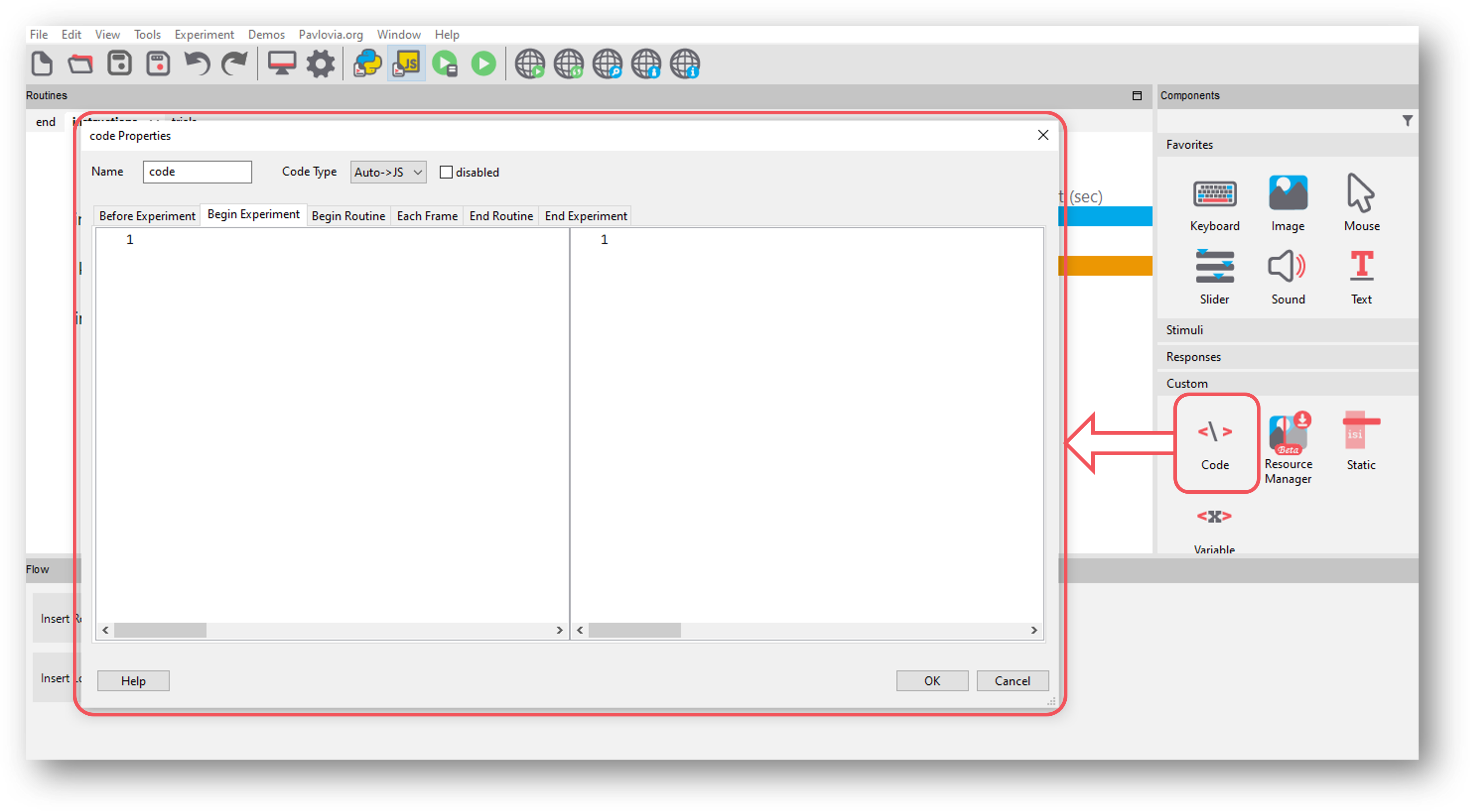
Fig. 15 Select the Code component from the Custom component drop-down
In the Begin Experiment tab, copy and paste the following code which will import the serial library and initiate PsychoPy’s communication with your serial port - be sure to change COM3 to the correct serial port address for your device:
import serial #Import the serial library
port = serial.Serial('COM3') #Change 'COM3' here to your serial port address
Now, copy and paste the following code component to your trials routine in the Begin Routine tab (or whichever routine you want to send triggers from):
stimulus_pulse_started = False
stimulus_pulse_ended = False
In the same routine, copy and paste the following code in the Each Frame tab - be sure to change stimulus in line 1 to match the name of the component that you want to send the triggers for:
if stimulus.status == STARTED and not stimulus_pulse_started: #Change 'stimulus' to match the name of the component that you want to send the trigger for
    win.callOnFlip(port.write, str.encode('1'))
    stimulus_pulse_start_time = globalClock.getTime()
    stimulus_pulse_started  = True

if stimulus_pulse_started and not stimulus_pulse_ended:
        if globalClock.getTime() - stimulus_pulse_start_time >= 0.005:
            win.callOnFlip(port.write,  str.encode('0'))
            stimulus_pulse_ended = True
This code will send a ‘1’ to your device at the onset of the stimulus component, and then reset back to ‘0’. You can change these values to whatever is meaningful to your data, including asking PsychoPy to pull the value from your conditions file.
Finally, in a routine at the end of your experiment (the Thanks for participating screen for example) copy and paste the following:
port.close()
We now recommend that you :ref: test your triggers <trigger_test>.
To check that everything works, we recommend that you set up a very basic experiment that looks similar to this:
Turn on your EEG recording device and start recording as you would in your actual experiment, and just check that you see triggers coming through.
It’s a good idea at this point to also check the timing of your stimulus presentation and your triggers using, for example, a photodiode for visual stimuli.
Doing these checks with a very basic experiment just means that you don’t accidentally change something on your real experiment file that you don’t want to, and also means you don’t have to disable components or sit through lots of instructions etc!
PsychoPy has components that allow you to connect and communicate with eyetrackers directly from Builder - without any code! These steps will guide you through how to set up, calibrate, and record from your eyetracker.
PsychoPy supports many of the commonly used eyetrackers, you can find out if yours is supported by following these steps:
Click on the Experiment Settings icon (the one that looks like a cog, near the top left-hand side of the Builder window).
Click on the Eyetracking tab:
The SR Research option is also known as Eyelink, so if you have an Eyelink device this is the option to choose.
When you’ve found your eyetracker, just select it and click OK.
If you want to test out your eyetracking experiment but don’t have an eyetracker with you, you can select MouseGaze. This will allow your mouse cursor to act as a gaze point on your screen, and so allow you to simulate eye movements without using an eyetracker. Then, when you’re ready to use your eyetracker, you can just select it from the Experiment Settings and run your experiment in the same way.
When you’ve selected your eyetracker from the drop-down menu, a set of options that are specific to that device will appear, such as the model and serial number of your device. Here we will follow through with the MouseGaze options:
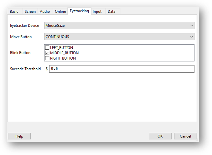
Choose which mouse button you’d like to use to simulate blinks by clicking on the boxes.
The Move Button option allows you to select whether PsychoPy monitors your mouse movement continuously, or just when you press and hold one of the mouse buttons.
The Saccade Threshold is the threshold, in degrees of visual angle, before a saccade is recorded.
When setting up your EyeLink you will first need to make sure you have the following set up:
An “Experiment” computer (this is the computer the experiment is run on) - set the IP address of this computer to 100.1.1.2
A “Host” computer (this is the computer where the EyeLink software runs) - set the IP address of this computer to 100.1.1.1
In your PsychoPy Experiment Settings > Eyetracking ensure you have SR Research selected, in the IP address use 100.1.1.1 (the IP of the host computer).
Before any communication can happen between the eyetracker and your experiment, the two computers must be connected via an ethernet cable and you need to check the two devices can communicate with one another. You can check the connection by opening the command prompt/terminal on the experiment computer and typing ping 100.1.1.1 if the connection is successful you will see that the pings are successfully returned. If you have trouble connecting at this phase you will want to trouble shoot by searching the returned error message.
Sometimes different eyetracking systems will have their own set of “screens” or “protocols” that they present. These are independant of what we can currently control from PsychoPy, which means that if you have made your experiment using MouseGaze, then move to the lab with the EyeLink and change the eyetracker to SR Research the instructions that you see at the start of the calibration may appear a little different to what you were expecting!
The general protocol you will see is shown below.
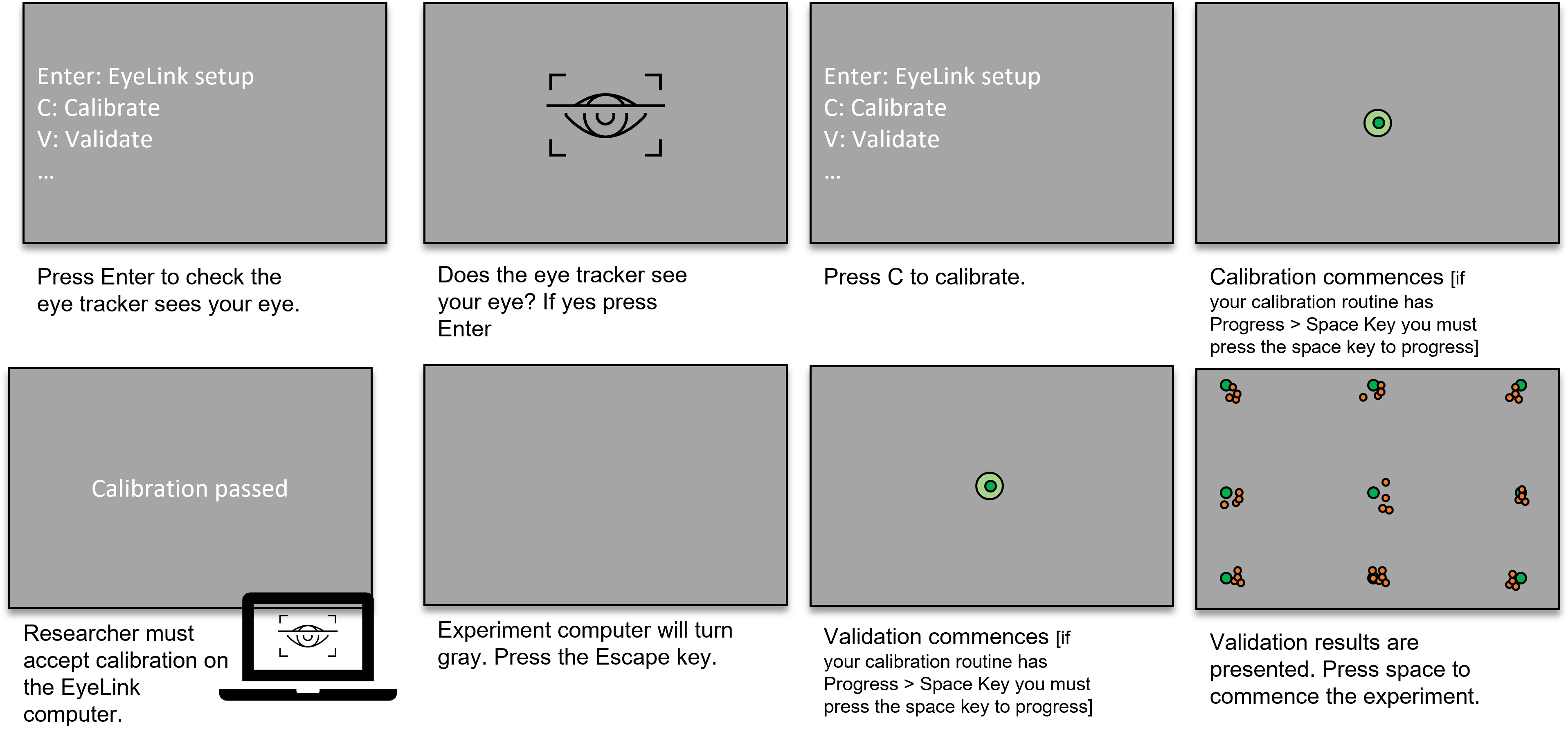
Fig. 16 The set of screens that will appear on your experiment presentation screen during calibration/validation, and what to press when.
You can find the eyetracker components in the eyetracker component drop-down on the right-hand side of the Builder window.
The first component to add is the ‘Eyetracker Record’ component as this starts and stops the eyetracker recording. Usually, you would add this component to your instructions routine or something similar, so that your eyetracker is set off recording before your trials start, but you can add them in wherever makes sense for your experiment:
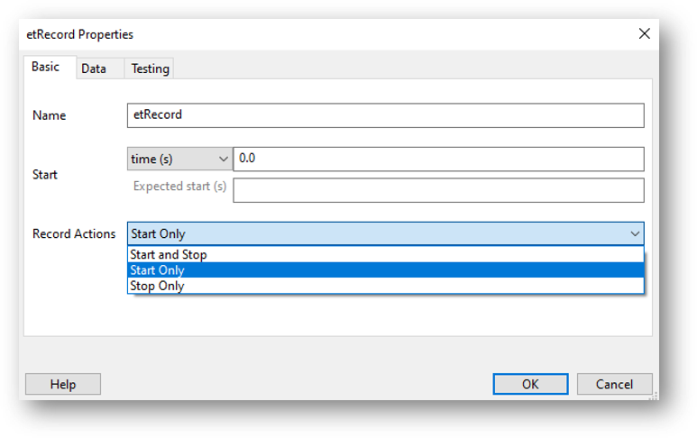
Fig. 17 You can choose whether you want this component to just start your eyetracker recording, just stop the recording, or whether you want the component to start the recording and then stop it after a certain duration.
Note
If you’ve started the eyetracker recording at the start of your experiment, be sure to add in another eyetracker record component at the end of your experiment to stop the recording too!
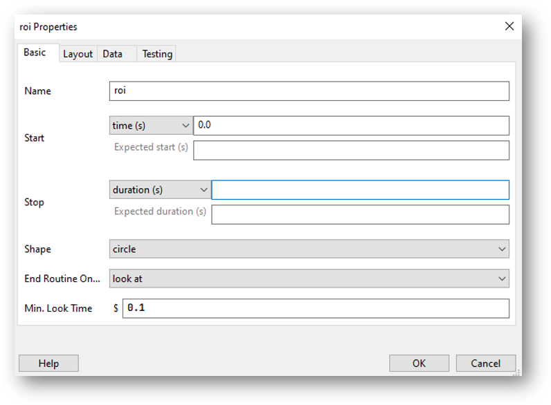
If you want to record information on gaze position, or you want your trial to move on when your participant has looked at or away from a target, you’ll need to add in an ROI component. The ROI component has lots of options - you can choose what you want to happen when the participant looks at or away from a certain part of the screen, what shape your ROI is etc. All of which can also be defined in your conditions file, just like any other component. Choose the options that fit the needs of your experiment. Here, the component is set such that when a participant looks at a circular target for at least 0.1s (set by the min look time), the trial will end:
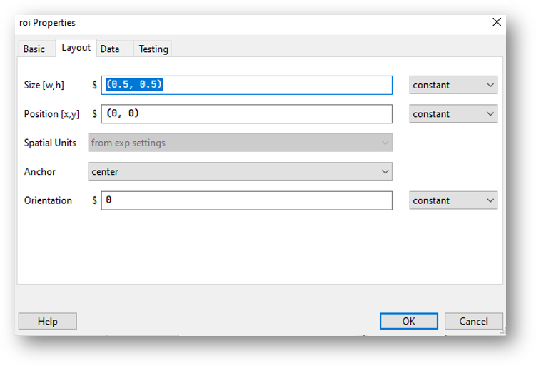
On the layout tab of the ROI component, you set the position and size of the ROI in the same way as you would set the position of any visual component:
It’s also vitally important that you calibrate and validate your eyetracker. To do this, you will use two standalone components: Eyetracker calibrate and Eyetracker validate.
These are a little different from other components in that they form a routine all on their own. You’ll need to add them in right at the start of your experiment Flow.
The Eyetracker calibrate component has all of the options you would expect from an eyetracker calibration:
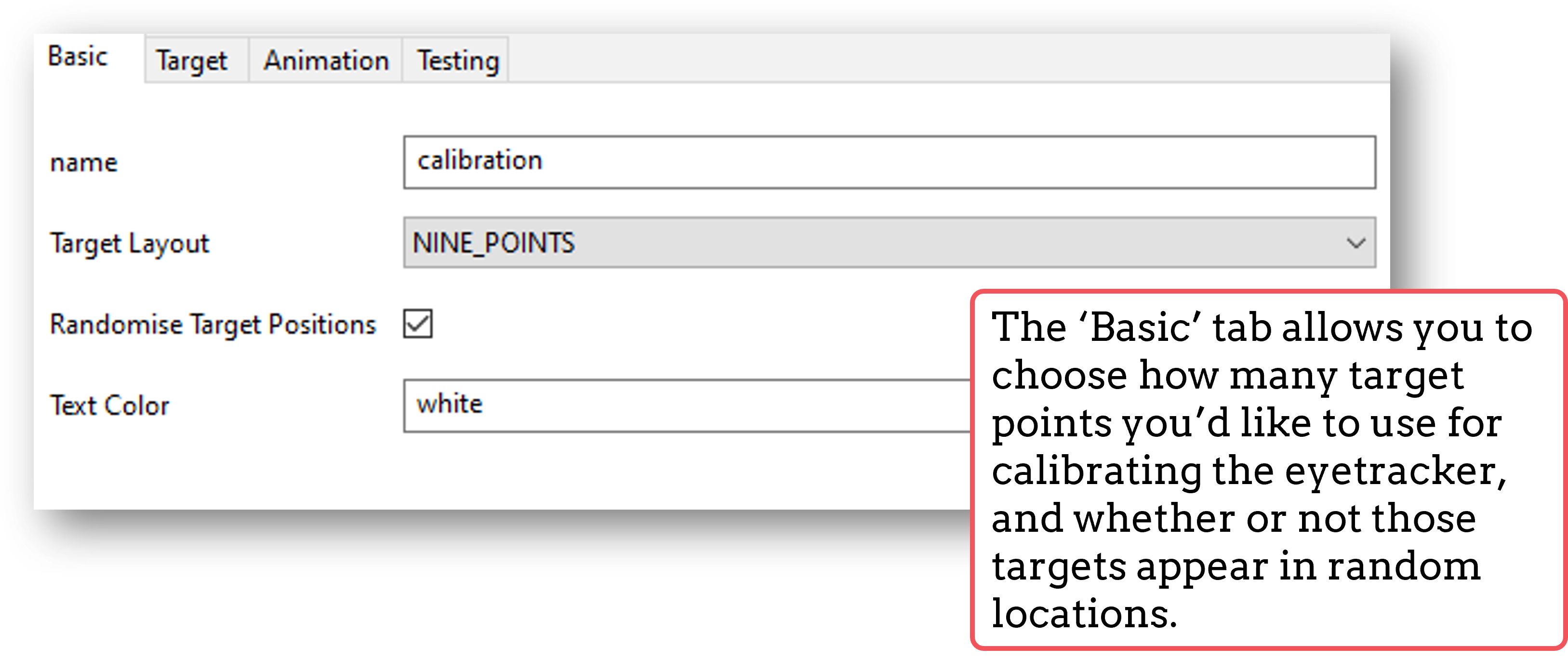
Fig. 18 Set the basic properties of the calibration routine here.
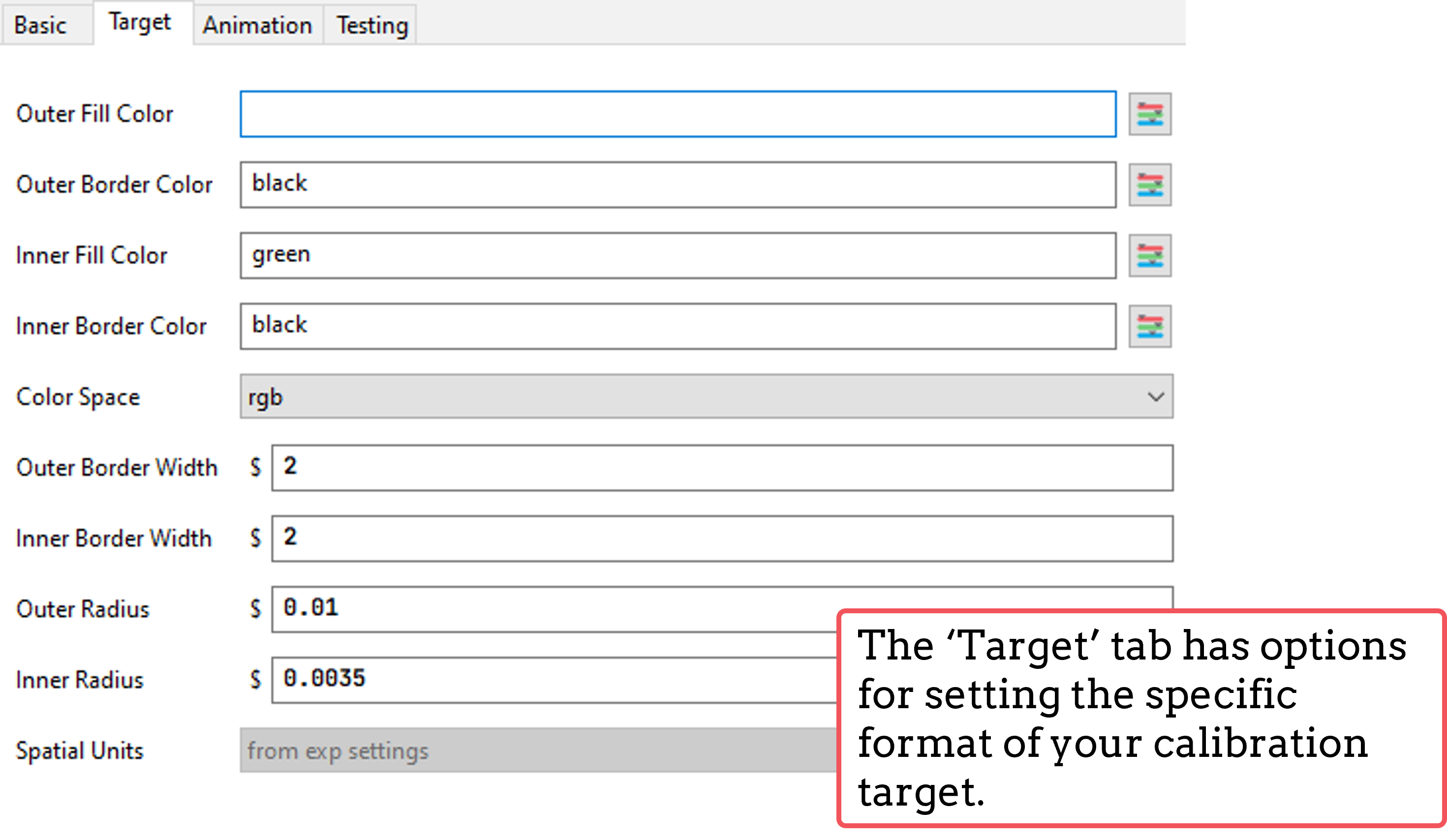
Fig. 19 Set the properties of the target on this tab.
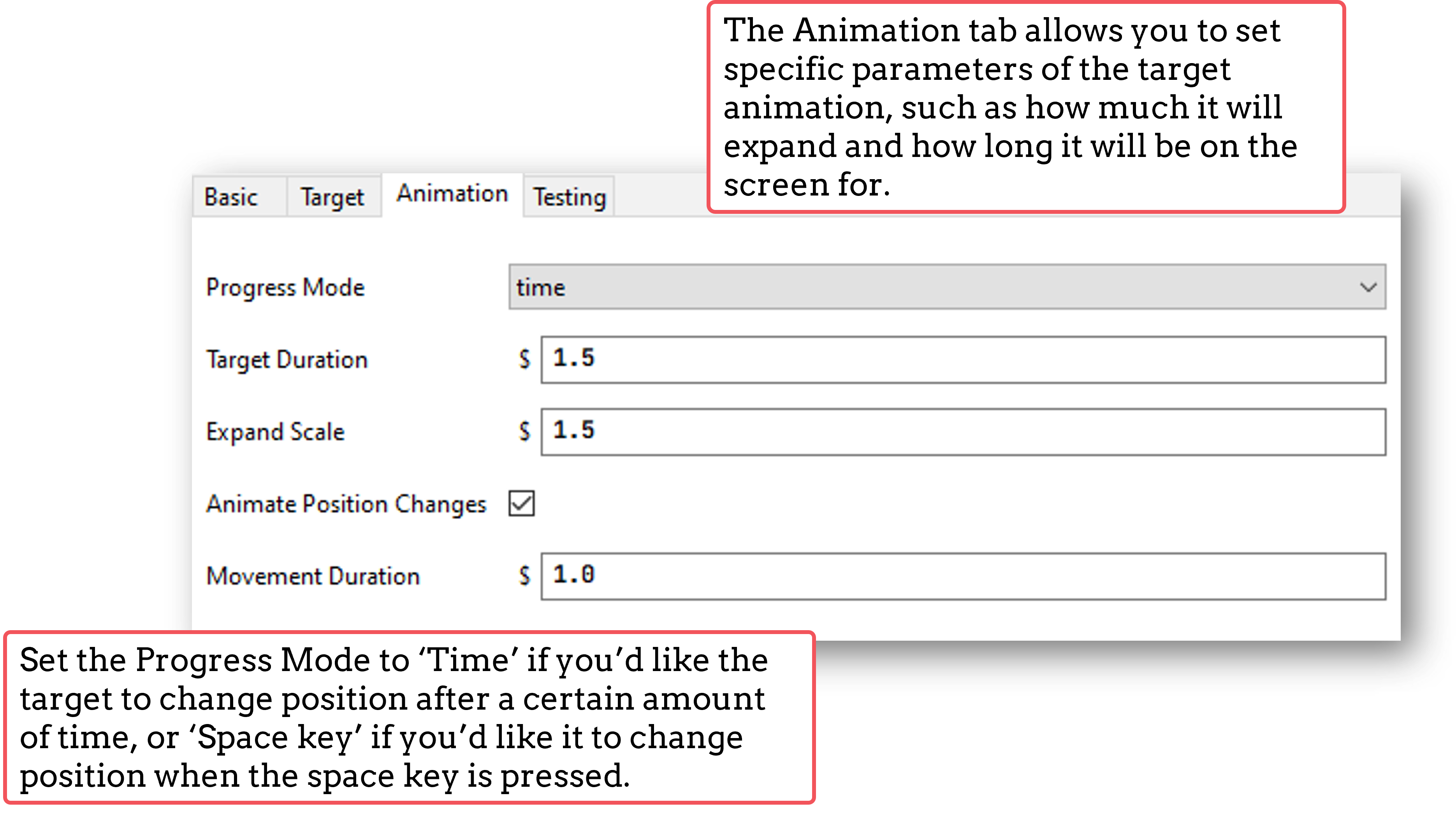
Fig. 20 This tab allows you to set the properties of the target animation.
The Eyetracker validate component, you’ll notice, is pretty much identical to the calibration component - that’s because it will use the calibration information to present the same screen to the participant to cross-check the recorded gaze position with the calibrated gaze position.
The Eyetracker validate component will then show the offset between the recorded and calibrated gaze positions. You’ll want these to be as close as possible to ensure that your eyetracker is recording gaze accurately.
The eyetracking data from the ROI will be saved in your usual data file. Extra columns are created and populated by PsychoPy, depending on what you’ve asked to record.
In the example below, the trial ended when a participant looked at a target on the screen. You can see what each column represents in the figure below:
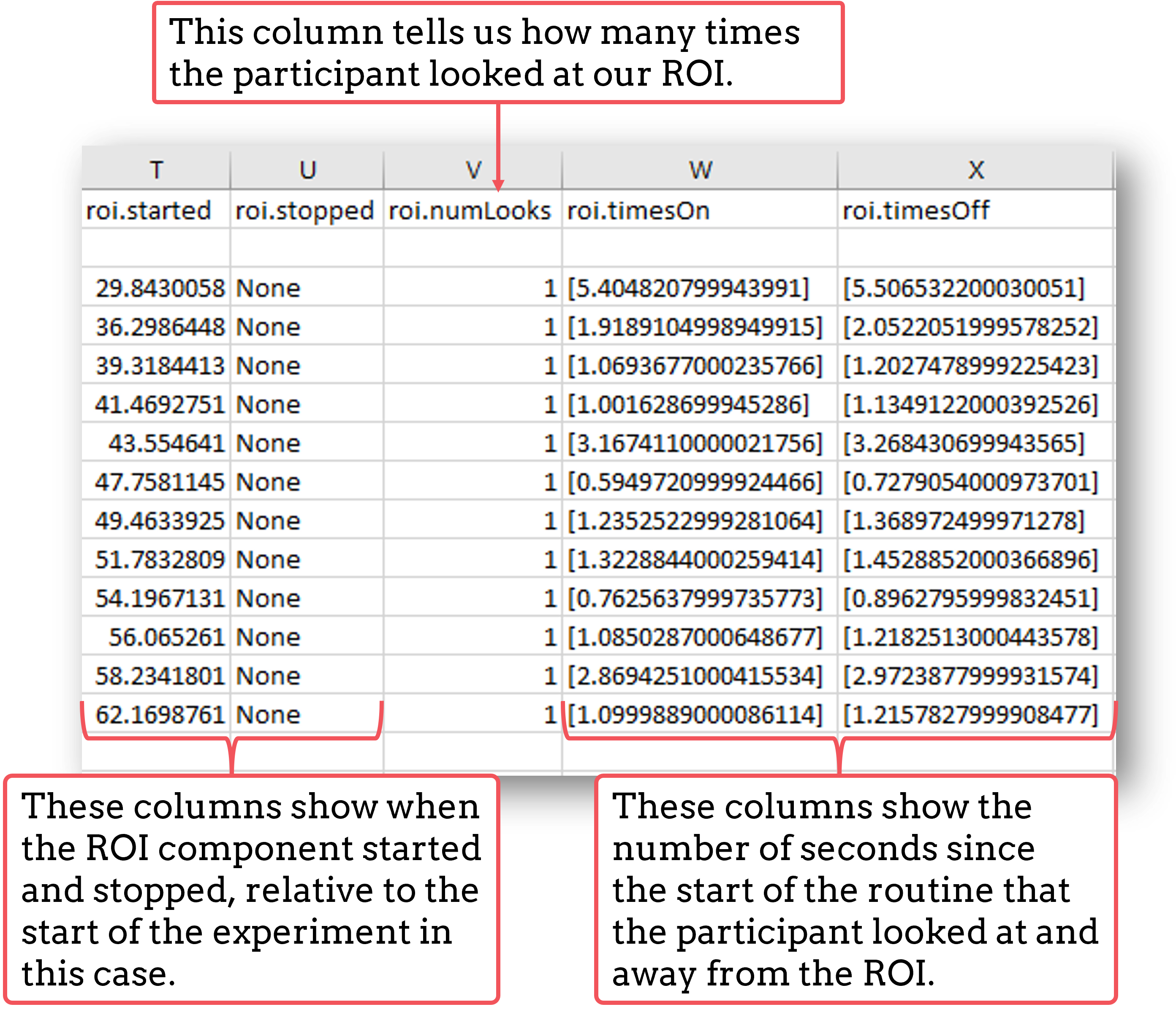
Fig. 21 The data output will vary according to what you’ve asked PsychoPy to record about gaze.
PsychoPy also provides the option to save your eyetracking data as a hdf5 file, which is particularly useful if you are recording a large amount of eyetracking data, such as gaze position on every frame for example.
To save eyetracking data as a hdf5 file, just click on the Experiment Settings icon, and in the ‘Data’ tab check the box next to ‘Save hdf5 file’.
fmri
arduino
To communicate with fNIRS, download this fantastic document from NIRx.
Arduino microcontrollers are a relatively cost-effective way to record biophysical responses to stimuli, such as galvanic skin response (GSR) or heart rate. This page will guide you through how to record information from an Arduino via a serial port connection.
This guide will cover how to set up your PsychoPy experiment only - for lots of tutorials on using your Arduino, and also how to download the open-source Arduino software, take a look at the Arduino website.
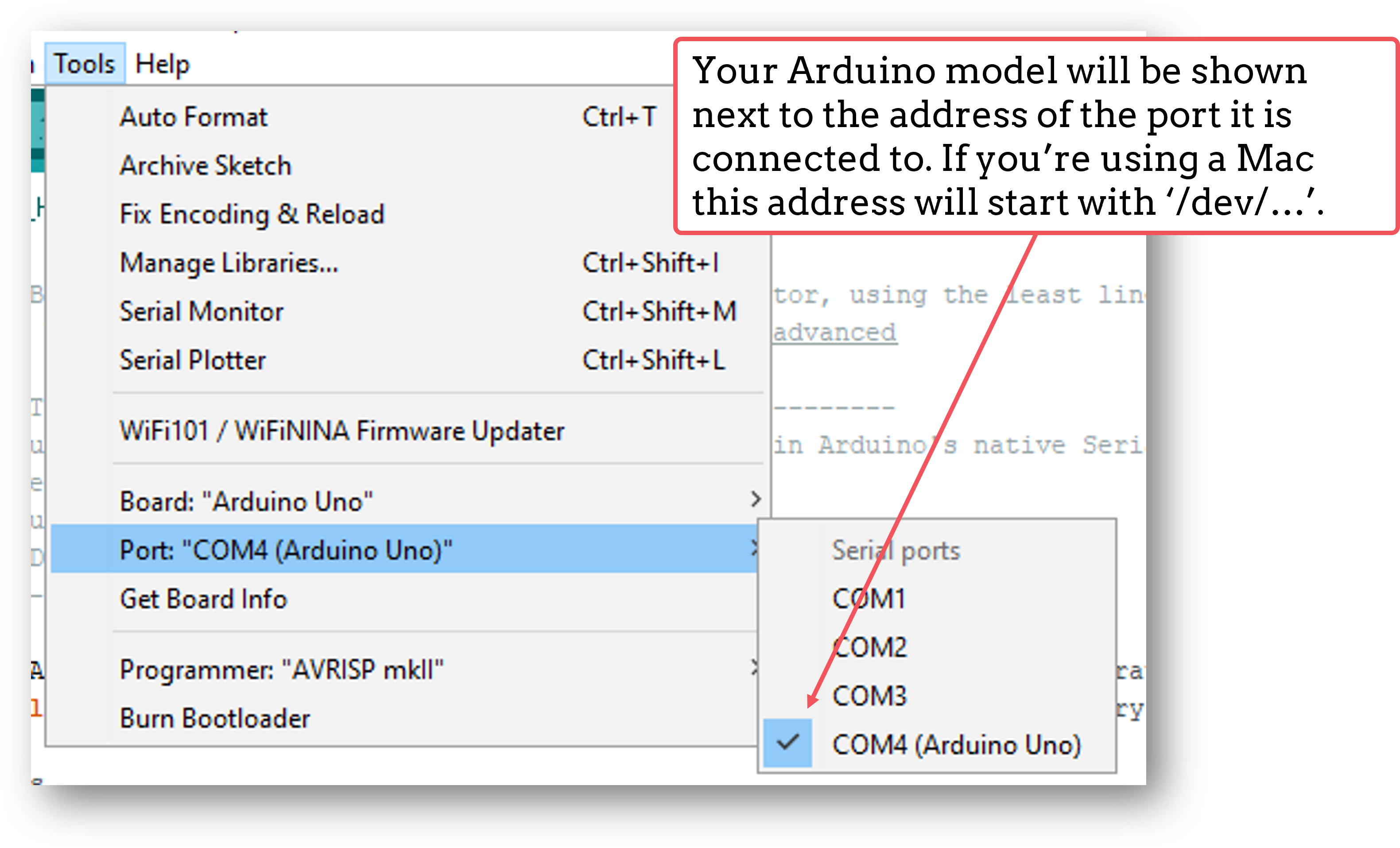
You can quickly find out the address of the serial port that your Arduino is connected to by opening the Arduino IDE and clicking on Tools at the top of the window, then down to Port. Here, the port that your Arduino is connected to will show the model of your Arduino next to it.
Let’s assume for this tutorial that we have a basic experiment set up where we are presenting an image stimulus to a participant, and we want to record their heart rate, via a module connected to an Arduino, during viewing.
The first thing we’ll need to do is initiate the communication between PsychoPy and the Arduino. We do this by adding in a code component to a routine at the start of the experiment (such as an instructions routine).
In the Begin Experiment tab of that code component, add the following code to import the necessary libraries:
import serial
import time
Then in that same code component, in the End Routine tab, we’re going to add in code to start the communication between PsychoPy and Arduino. This will also initialise the Arduino:
port = serial.Serial('COM4', 9600) #Change 'COM4' here to the address of the serial port your Arduino is connected to. '9600' is the Baudrate, and this should be set to the same rate as that of your Arduino.
time.sleep(1) #Give the Arduino some time to wake up!
Next, we’ll add a code component to our trial routine. This component will record the information that the Arduino is sending over the serial port. We’ll add it here to record information on every frame when the stimulus is presented, as we want to know how the participant’s heart rate changes over the course of the stimulus.
In the Begin Routine tab of this code component, add the following code to set up a list in which you’ll record your data:
res = []
Then in the Each Frame tab of that same code component, add the following to get PsychoPy to read the information sent over the serial port by Arduino:
res.append(port.readline())
Now in the End Routine tab, we’re going to ask PsychoPy to save the data to our .csv data file. But in this case we want only the numbers that are sent. You might have noticed that Arduino sends things like ‘\n’ along with its data. This isn’t always helpful for analysis, so we’ll ask PsychoPy to ignore those values and save only a list of integers in our data file:
numbers = [] #Make a list to put the numbers only in

 for i, string in enumerate(res):
     for word in string.split():
         if word.isdigit():
             numbers.append(int(word))
 thisExp.addData('heart_rate', numbers) #Add the list to our data file - 'heart_rate' will be the name of this column in our .csv file.
Finally, we’re going to close the port when the experiment ends. To do this, add the following to the End Experiment tab of any code component:
port.close()
You should now have an experiment that reads and records the information being sent by an Arduino. Here we used heart rate as an example, but this code can easily be adapted to record any information that your Arduino is sending.
Due to the haemodynamic response being comparatively sluggish relative to scalp voltage changes, fMRI studies don’t typically require sub-millisecond timing precision within a trial like EEG studies do.
However it is important that an fMRI study has consistent timing across trials so that the scanner sequence remains in sync with an experiment.
Rather than programming your PsychoPy experiment to send triggers to some hardware in the same way as EEG, with fMRI you would want to set up your experiment so that it waits until it has detected when the scanner has sent out a trigger before moving on to present trials.
Before doing anything else, it’s important that you know how the scanner you’ll be using will emit these triggers, and whether these are converted to some other signal such as characters on a serial port or a simulated keypress. In general, there are at least 3 ways a scanner might send a trigger to your experiment:
Emmulate a keypress.
Via parallel port
Via serial port
A Routine to detect fMRI triggers is really simple to set up. Regardless of the method your scanner uses to send the triggers, you’ll just need a Routine that waits until it’s detected the trigger before moving on. Create a new Routine and insert a Text component that says ‘Waiting for Scanner’.
Insert a Keyboard component to your ‘Waiting for Scanner’ Routine. In ‘allowed keys’ use the key that the scanner will send e.g. if the scanner sends ‘5’ allowed keys will be ‘5’.
Now, when the keypress is detected, the ‘Waiting for Scanner’ screen will end. Although, be careful! PsychoPy doesn’t know the difference between the emulated key presses sent from the scanner and key presses made by a human being! So take care not to type on the keyboard connected to the PsychoPy computer whilst your experiment runs to avoid your key presses being mistaken for triggers.
Insert a code component to your ‘Waiting for Scanner’ Routine
In the Begin Experiment tab of the code component, add the following code to set up the Parallel Port:
from psychopy.hardware.parallel import ParallelPort
triggers = ParallelPort(address = 0x0378) #Change this address to match the address of the Parallel Port that the device is connected to
pinNumber = 4 #Change to match the pin that is receiving the pulse value sent by your scanner. Set this to None to scan all pins
In the Each Frame tab of the same code component, add the following code to check for triggers:
if frameN > 1: #To allow the 'Waiting for Scanner' screen to display
    trig = triggers.waitTriggers(triggers = [pinNumber], direction = 1, maxWait = 30)
    if trig is not None:
        continueRoutine = False #A trigger was detected, so move on
The ‘Waiting for Scanner’ message will now remain on the screen until the trigger is received from the scanner.
Insert a code component to your ‘Waiting for Scanner’ Routine
In the Begin Experiment tab of the code component, add the following code to set up the Serial Port:
from psychopy.hardware.serial import SerialPort
triggers = SerialPort('COM3', baudrate = 9600) #Change to match the address of your Serial Port
trigger = '1' #Change to match the expected character sent from your scanner, or set to None for any character
In the Each Frame tab of the same code component, add the following code to check for triggers:
if thisTrigger in self.read(self.inWaiting()):
    continueRoutine = False #Our trigger was detected, so move on
The ‘Waiting for Scanner’ message will now remain on the screen until the trigger is received from the scanner.
In fMRI studies, it’s important that the scanner runs remain in sync with the experiment, especially if you are only waiting for the scanner to send a trigger once at the start of the experiment.
PsychoPy implements a feature called non-slip timing to help with this (you can find out more about what this is and why it’s important here.
If you set your trial Routines to have a definite end-point (e.g. all components within a trial Routine will end after 5 seconds), you’ll notice that the colour of the Routine in your Flow changes from blue to green. This is your indication that the Routine is making use of non-slip timing.
If you can’t set your Routines to have a fixed duration (for example if a trial ends when a participant makes a response), it’s a good idea to insert a ‘Waiting for Scanner’ Routine at the start of every trial so that you know that each trial has been synced with your scanner’s trigger.